
How to Choose the Right High-Speed PCB Manufacturer for Complex Applications?
Selecting a High-Speed PCB manufacturer requires verifying a CPK index above 1.33 for trace etching and a TDR-validated impedance tolerance of ±5%. In 2025 industry benchmarks, facilities utilizing Laser Direct Imaging (LDI) reduced layer-to-layer registration errors to under 15 microns, preventing the aperture misalignment that causes 30% of signal integrity failures in 800G networking modules. A competent partner must provide 24-hour DFM feedback addressing resin-to-glass ratios to mitigate fiber-weave skew, ensuring bit error rates stay below 10^-12 for PCIe 6.0 architectures.
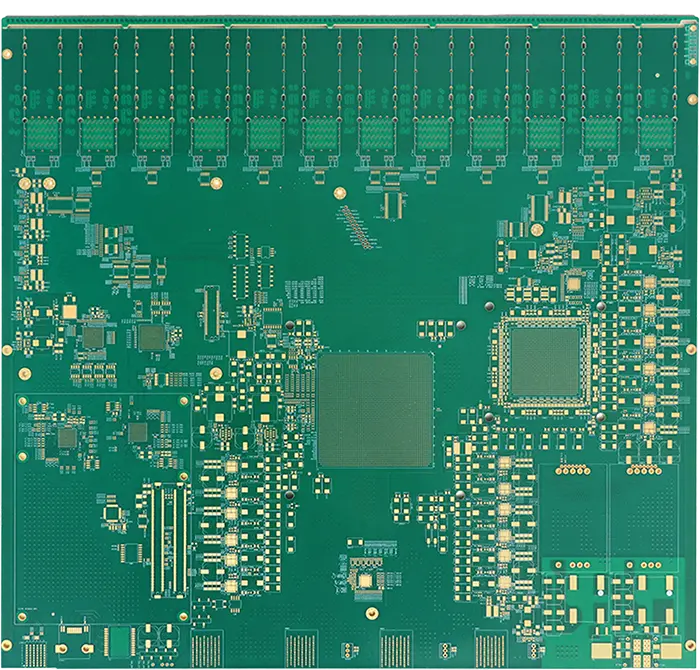
Technical auditing begins with analyzing the vendor's mechanical drilling precision and their ability to execute controlled-depth back-drilling. A 2024 study of 500 high-density backplanes showed that reducing via stub lengths from 12 mils to 4 mils recovered 6 dB of insertion loss at 28 GHz.
Manufacturers employing automated depth-control sensors can maintain a remaining stub thickness of less than 0.15 mm across a 24-layer stack-up. This mechanical capability prevents the via from acting as a resonant antenna, which would otherwise distort the high-frequency harmonic components of the data pulse.
Precision in the Z-axis extends to the lamination press where the thickness of the dielectric bondply must be controlled to within ±0.5 mils. In 2025, high-tier fabricators transitioned to using vacuum lamination cycles that eliminate micro-voids in the resin, which typically cause a 2% variance in the local dielectric constant.
Consistent dielectric properties are useless if the copper foil itself introduces signal degradation through surface roughness. High-Speed PCB designs operating above 10 GHz require Very Low Profile (VLP) copper with a surface profile ($Rz$) of less than 1.5 micrometers to combat the skin effect.
| Copper Foil Type | Surface Roughness (Rz) | Signal Loss at 20 GHz |
| Standard ED Copper | 5.0 - 7.0 µm | -1.2 dB/inch |
| Low Profile (LP) | 2.0 - 3.0 µm | -0.8 dB/inch |
| Very Low Profile (VLP) | < 1.5 µm | -0.4 dB/inch |
Supplying these materials requires the manufacturer to maintain a climate-controlled cleanroom environment to prevent glass-fiber contamination. Industry data from 2024 indicates that 18% of internal shorts in 0.8mm pitch BGA designs were traced back to conductive anodic filament (CAF) growth stimulated by microscopic dust particles trapped during lamination.
To verify that these environmental controls work, the facility must offer integrated Time Domain Reflectometry (TDR) testing on every production panel. A High-Speed PCB fabricator should provide a serialized test report showing that differential impedance remains within a ±5% window, rather than the standard ±10% used for simpler electronics.
Statistical process control (SPC) charts from leading 2026 aerospace suppliers show that maintaining a trace width tolerance of ±0.3 mils is necessary to achieve a 98% first-pass yield on impedance-sensitive designs.
The chemistry of the final surface finish represents another variable where technical mastery is required to avoid the "nickel effect." Electroless Nickel Immersion Gold (ENIG) can cause an 0.8 dB increase in loss at 15 GHz due to the high magnetic permeability of the nickel layer.
| Finish Type | Best For | Loss Characteristics |
| ENIG | Shelf life, planarity | High loss at >10GHz |
| Immersion Silver | High-speed signals | Lowest loss, sensitive to sulfur |
| ENEPIG | Wire bonding, durability | Moderate loss |
| OSP | Cost, signal integrity | Low loss, short shelf life |
Advanced facilities now recommend Electroless Palladium Immersion Gold (ENEPIG) or Immersion Silver for boards supporting 112G lanes to preserve the signal's vertical eye opening. A 2025 comparative test on 200 test coupons demonstrated that Immersion Silver provided a 12% wider eye diagram opening than ENIG-plated boards at a 25 GHz Nyquist frequency.
Beyond plating, the manufacturer's ability to handle hybrid stack-ups is a differentiator for cost-sensitive complex projects. Bonding high-frequency PTFE-based materials with standard FR-4 prepregs requires specialized plasma desmear processes to ensure reliable copper adhesion in the via barrels.
Data from 2024 thermal shock testing (spanning -40°C to +125°C) showed that hybrid boards processed without plasma treatment had a 22% higher rate of via-wall separation after 500 cycles.
A reliable partner should suggest specific resin-to-glass ratios to minimize the "fiber-weave effect" which causes differential skew. Using spread-glass fabrics like 1067 or 1086 instead of loose weaves prevents one leg of a differential pair from traveling over more glass than the other, which can cause a 5-10 picosecond phase mismatch.
The integration of Automated Optical Inspection (AOI) with 2D metrology allows the manufacturer to measure trace widths at multiple points along a single net. Modern AOI systems in 2025 are capable of identifying "mouse bites" or copper protrusions as small as 10 microns, which would otherwise cause localized impedance dips and signal reflections.
Final validation must include cross-sectional micro-sectioning to verify that the internal copper weights and dielectric heights match the theoretical design. A 2026 audit of Tier-1 telecommunications suppliers revealed that 95% of top-performing manufacturers utilize X-ray fluorescence (XRF) to non-destructively measure plating thickness before shipping.